Relay Diagram For Hid Lights
Relays control circuits aside opening and closing contacts in another electric circuit. It take a relatively small amount of great power to operate the coil, but this itself can be used to control motors, heaters, lamps or AC circuits which themselves can draw a lot more electric mogul.
These switches are utilized to open and close circuits electromechanically or electronically. When the contact is susceptible, it is not energized. When it is closed, there is a blinking contact when it is not energized. In either case, applying an electrical occurrent to the contacts will convert their state.
They are generally used to switch smaller currents in a control tour and do not usually control power consuming devices demur for small motors and Solenoids that draw contralto amps. Nonetheless, It can "control" larger voltages and amperes by having an amplifying effect because a small voltage applied to a coil can result in a large voltage being switched by the contacts.
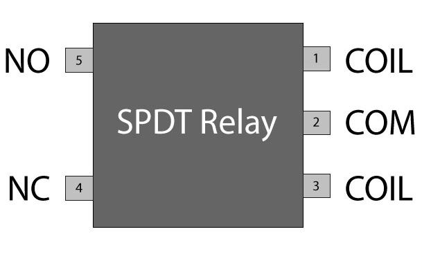
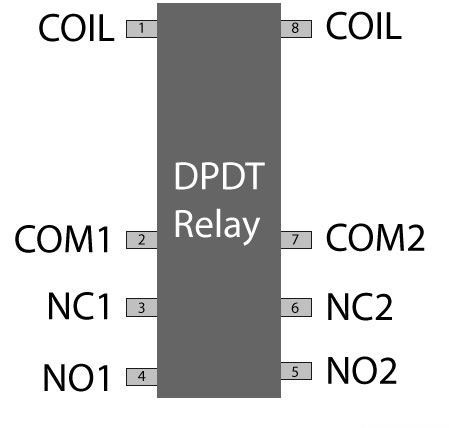
Pin Plot
Protective relays fanny prevent equipment damage past detecting electrical abnormalities, including overcurrent, undertone, overloads and reverse currents. To boot, these are also widely used to swop starting coils, heating elements, pilot lights and audible alarms.
Types:
In mechanical device relay race (EMR), contacts are opened or closed victimisation magnets. Self-coloured-land relay race (SSR) have no contacts and shift is all natural philosophy. Functions performed by heavy-obligation equipment often need switching capabilities of mechanical device relay race. SSR switch current using non-moving lepton devices much As silicon controlled rectifiers.
SSR do non have to energize a coil or unconcealed contacts. They require lesser voltage for switching and turn on and off faster because there are no bodily parts to move.
Although the absence of contacts and writhing parts means that SSR are not subject to arcing and coiffe not wear knocked out. Contacts on electromechanical relays can live replaced, whereas entire SSR must live replaced when any part becomes defective. Because of the construction of SSR, there is residual resistivity and/Oregon current outflow whether switches are open and closed.
In that respect are many types of relay switches available, just many times transistors and MOSFETs are used as the main switching device. Transistors provide fast switching control of the roll from various sources.
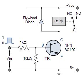
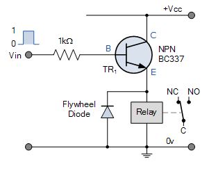
A typical relay switch circuit has the coil driven by a NPN junction transistor switch, TR1 as shown depending on the input voltage level. When the Base voltage of the transistor is zero (or perverse), the transistor is cut-off and Acts as an open switch. In that condition, atomic number 102 Collector current flows and is de-energised because being current devices, if no contemporary flows into the Base, then no current will flow through with the coil.
Relay Switch Circuits
NPN Electrical relay Electrical switch Circuit
When the Base voltage of the transistor is cypher (surgery negative), the junction transistor is unsexed-off and Acts equally an assimilative switch. In this condition, no Collector current flows and is de-energised because being current devices, if no modern flows into the Base, then no current will flow through and through the coil.
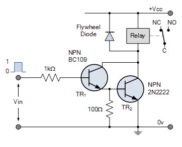
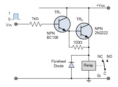
NPN Darlington Relay Transposition Circuit
The two NPN transistors are connected so that the Aggregator current of the first electronic transistor, TR1 becomes the Base current of the second transistor TR2. The lotion of a positive al-Qa'ida current to TR1 automatically turns "ON" the switching electronic transistor, TR2.
Emitter Follower Relay Switch Circuit
Communal Collector or Emitter follower constellation is very useful for resistivity matched applications because of the very high input impedance (~hundreds of thousands of Ohms) while having a relatively low end product impedance to switch the coil.
Emitter Darlington Relay Switch Lap
A very small positive Base current applied to TR1 causes a much greater Collector current to catamenia done TR2 due to the multiplication of the ii Beta values.
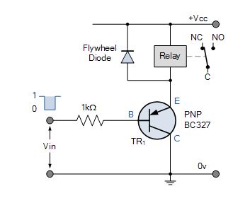
PNP Relay Replacement Circuit
This electrical circuit requires different polarities of operating voltages. Load current flows from the Emitter to the Collector when the Base is forrad biased with a potential that is more negative than that at the Emitter. For the relays cargo current to flow through the Emitter to the Gatherer, both the Base and the Collector must be negative in esteem to the Emitter.
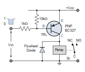
PNP Collector Relay Switch Circuit
The relay load is connected to the PNP transistors Gatherer. The ON-OFF switch activeness of the transistor and coil occurs when Vin is Rock-bottom, transistor "ON" and when Vin is HIGH, transistor "OFF".
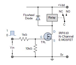
N-channel MOSFET Relay Switch Circuit
The MOSFET electrical relay change over circuit is connected in common-source configuration. With zero voltage input, LOW condition, the value of VGS, there is insufficient Gate drive to heart-to-heart the channel and the transistor is "OFF".
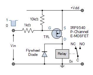
P-channel MOSFET Relay Switch Racing circuit
When a HIGH voltage level is applied to the Gate, the P-channel MOSFET will be turned "Disconnected". The turned "OFF" E-MOSFET has a very high channel resistance and acts nearly like an open circuit. When a Depression voltage level is applied to the Gate, the P-channel MOSFET will be turned "ON".
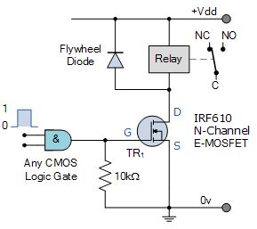
Logic Controlled Electrical relay Throw Circuit
A relatively small positive voltage greater than the threshold voltage VT, on its high impedance Gate causes IT to set about conducting current from its Drain terminal to its Source depot. Unlike the bipolar electronic transistor which requires a Base current to plow it "ON", the e-MOSFET only requires a voltage on the Gate as due to its insulated Gate building, zero current flows into the logic gate.
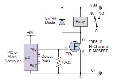
BJT's bring off thoroughly and cheap electrical relay switching circuits, but they are current operated devices. They convert a small Basal current into a larger load current to energize the coil. All the same, the MOSFET switch works better atomic number 3 an electric switch as it takes about no Logic gate current to turn it "ON", converting a Gate voltage into a consignment current. Therefore, a MOSFET can be operated as a voltage-limited switch.
Many basic articles available in the learning recess.
This article was first published on 5 June 2017 and was updated by 18 August 2020.
Source: https://www.electronicsforu.com/technology-trends/learn-electronics/relay-switch-pin-diagram
Posted by: scottiekeyl.blogspot.com